Urban Tapestries - Feral Robot Client Architecture
Technical report of a Feral Robot prototype, 2nd generation
| Author: | Dima Diall & Dmitrios Airantzis |
|---|---|
| Organization: | Proboscis & Birkbeck College |
| Date: | 10 March 2006 |
| Version: | 1.1 |
Abstract
This report provides technical documentation for a prototype mobile environmental sensor that integrates with the Urban Tapestries public authoring system -- the Feral Robot, version 2. Descriptions of the main requirements, as well as the steps in the hardware/software platform development are presented.
Overview
Introduction
In the context of the Urban Tapestries (UT) project, Proboscis in collaboration with Birkbeck College developed a mobile sensor prototype -- dubbed "feral robot" -- capable of wirelessly uploading real-time, geo-referenced environmental data into the UT public authoring servers. Interested parties can visualize the collected data (e.g. air quality, etc) overlaid on a geographical map.
The first generation feral robot, developed by Natalie Jeremijenko, adopted an autonomous behaviour, roaming in the direction where the on-board sensor detected greater pollution concentration. However, this original system was based on a very simple microcontroller (PIC) that is unlikely to support real-time data communication using modern wireless networking technologies, thus making it unsuitable for integration with the UT public authoring framework.
For the second generation feral robot, documented in this report, due to time and funding constraints a key simplification to the requirements was defined to complete a working proof of concept: the autonomous mobility feature was sacrificed. The system was, instead, simply mounted on a remotely controlled all-terrain vehicle, without any interfacing to the car's control module.
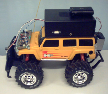
Feral robot prototype, version 2.
Requirements
The basic requirements outlined for the system prototype were defined as follows:
- Small, embeddable computer with enough resources to run a minimal GNU/Linux operating system (for ease of software development/prototyping).
- A set of environmental sensors are to be attached to the system via an analog/digital converter (a multi-channel ADC with at least 10-bit resolution and a few Hz of sampling rate).
- A GPS receiver to acquire the current geographic position and correlate it with the data sampled from the sensors.
- The collected data must be wirelessly transmitted to the UT server via TCP/IP networking.
- The entire system must be capable to run off batteries and mounted on the target vehicle/robot (at this stage, the vehicle will be remotely controlled and carry a separate power source).
Regarding the wireless communication between the mobile sensor system and the UT server systems, for prototyping purposes wi-fi (IEEE 802.11) was selected due to common software support available under GNU/Linux. Also, wi-fi internet access was within easy reach from the target demonstration workshop location through mesh networking. Nevertheless, other wireless networking technologies could be employed, such as GSM/GPRS, etc.
Architecture
The feral robots fit into a similar client/server paradigm underpinning other applications within the UT public authoring system. One or more feral robots act as clients sending real-time data to a UT server. These geo-referenced, environmental data is written to a database for later retrieval via a web interface.
A very simple UDP-based protocol was devised for communication between the feral robots and the UT server. Basically the clients are programmed to periodically sample their sensors and the GPS receiver and, for each reading, packages the data into a UDP datagram, that is then sent to the server. The protocol, in its version 1, defines a packet structure with the following data fields (details in appendix Packet Format):
- Status information
- Client identification (MAC address)
- Latitude/Longitude
- Time stamp
- Sensor type and value
More details about the Feral Robots sub-project can be found at the following website: http://socialtapestries.net/feralrobot/
Aim and Audience
This reports attempts to describe the feral robot prototype with sufficient technical detail to enable its reproduction and/or adaptation for similar types of application.
The remainder of this report assumes that the reader has at least some degree of familiarity in system administration and programming on GNU/Linux (or other UNIX-based) environments. Furthermore, experience with computer hardware in general is required, as well as an understanding of basic concepts of electricity and electronics.
Finally, documentation for the hardware and/or software involved must be referred to on an as needed basis, including but not limited to product datasheets, user guides, technical manuals, etc.
Hardware Setup
This chapter outlines the hardware components used to build this second generation feral robot prototype. Initially, several alternative hardware platforms were considered to host the client software, as documented in an earlier report where more details on the rationale are available.
The gumstix platform -- which includes a customized GNU/Linux distribution with out-of-the-box support for its hardware features -- was selected as the cornerstone to assemble this prototype. A summary of the hardware setup follows:
- Linux-based system: gumstix connex 400xm-bt single-board computer with stackable add-on boards for extended I/O capability, running the main feral robot client application.
- Environmental sensors: Figaro AM-4-4161 (carbon dioxide gas concentration evaluation module) and Figaro AMS-2100 (air quality sensor), attached to ADC pins on the robostix add-on board.
- GPS receiver: external bluetooth device, wirelessly linked to main gumstix system.
- Wireless TCP/IP networking: Netgear MA701 wi-fi CF card, connected on gumstix netCF add-on board.
- System integration: The above components are supported by a custom-built electronic circuit board and a battery power supply; finally, the package is mounted independently on top of an all-terrain R/C vehicle.
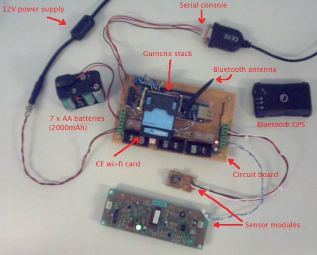
Overview of all relevant hardware components used in this prototype, prior to packaging and mounting.
The following sections provide further detail on the main hardware components, focussing mainly on the actual prototype developed. Most of design decisions were constrained not only by time and budget, but also by reasons of practicality and ease of implementation of this proof of concept. Naturally, many aspects can and must be adjusted or changed altogether to meet the requirements of a specific target application -- some of these possibilities are pointed out throughout the text.
Gumstix Components
The following stack of gumstix boards was used in this prototype [1]:
- connex 400xm-bt: main processor board (80x20x6mm in size) featuring an low-power Intel XScale processor with maximum clock frequency of 400MHz, 64 MB of RAM, 16MB of flash memory, and a bluetooth interface (antenna included).
- robostix (with headers): add-on board featuring an AVR ATmega128 microcontroller unit (MCU) with analog to digital capability (10-bit resolution ADC, with 8 channels).
- netCF: add-on board with integrated ethernet port and CompactFlash slot (suitable for a wi-fi card with the same interface).
| [1] | Commercial information about gumstix products is available at http://gumstix.com, while technical details are shared on the user community website at http://gumstix.org/tikiwiki. |
The gumstix connex board sits the middle of the stack, connecting to the robostix via the 60-pin Hirose I/O header on one side, and to the netCF via the 92-pin bus header, on the opposite side.
The high-end connex 400xm-bt platform was selected to offer more flexibility during development and prototyping, chiefly in terms of more flash memory for troubleshooting tools and support for using a bluetooth GPS receiver (more details below). Alternative platforms, slower and with less flash memory (e.g. connex 400-bt model with only 4MB of flash), can also be employed by sacrificing some extra software packages (discussed further in the section Gumstix Linux). It must be also noted that the XScale processor's (successor of ARM) can be adjusted to lower clock frequencies (e.g. 200 or 100 MHz) to consume less power.
The robostix runs independently from the main gumstix board, with dissimilar processors: AVR Atmega128 and Intel XScale, respectively. To enable exchange of data between programs running on the two boards, both were interconnected through one of their serial ports: UART0 on the robostix, and STUART on the gumstix. The figure below illustrates which pins on the robostix header need to be connected:
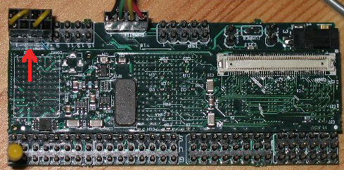
A gumstix stacked with a robostix: serial port interconnect at top left (image from www.gumstix.org).
The netCF board was chosen to enable using both, ethernet and wi-fi networks during development and testing. Alternatively, the much cheaper cfstix board can be used if only wi-fi networking is required.
Other gumstix components were used during development, namely the tweener board to provide serial console access, a corresponding null-modem cable (with mini-DIN and DB-9 connectors) and a 5V power supply. However, the use of a dedicated circuit board in the final setup eliminates the need for these elements.
Extra Components
This section briefly describes other relevant components to the prototype's hardware setup.
Wi-Fi Interface
The CompactFlash wi-fi interface used was the Netgear MA701 -- now discontinued --, which is the only one "officially" supported. Nevertheless, it should still be possible to procure them through eBay or similar websites.
Other gumstix customers also reported success with different cards, such as Belkin F5D6060 and AmbiCom WL1100-CF. During the first weeks of this project there were attempts to provide support for the Symbol Spectrum24 card using the Linux ORiNOCO driver, but without success in the amount of time available (more in Feral Robot Buildroot Branch).
GPS Receiver
The choice to use a bluetooth GPS receiver, was based mainly on the fact that two such units were available to the the project at its very outset. These are portable devices with independent battery power, providing NMEA-compliant positioning data over a bluetooth communication interface.
Other types of GPS receiver could be attached to the system via a serial port (e.g. HWUART) and powered from same circuit board. The gpsd software (see Feral Robot Buildroot Branch) used to access GPS positioning data can be configured to support various formats, so non-NMEA receivers can be used too.
Sensor Modules
Two Figaro sensors were used in this prototype:
- Figaro AM-4-4161: an evaluation module (with on-board microprocessor that linearises results) for the TGS-4161 carbon dioxide (CO2) gas sensor. The module's output range is 0.0 to 3.0V corresponding to a gas concentration of 0 to 3,000 ppm. After power-on, this sensor module needs a 2-hour warm-up period (for sensor output calibration).
- Figaro AMS-2100: a precalibrated air quality gas sensor module. The output range is 0.7 to 2.5V, but the datasheet does not provide details on how the results are to be interpreted.
Obviously, the choice of sensors will depend on the type of pollutants to be detected or measured in each case. Up to 8 different inputs can be attached in this prototype's setup.
Circuit Board
A custom electronic circuit board (10x16cm) was developed in order to underpin all others components of the prototype (further information about design and layout provided in Circuit Details). The purpose of this support circuit board is to:
- provide power to the main gusmtix stack assembly,
- provide power to the sensors,
- charge and maintain the battery cells,
- provide serial console access to the gumstix system,
- form the mechanical host of the gumstix stack.
The robostix is screwed to the circuit board, and the whole gumstix stack (robostix + connex + netCF) is carefully secured with two extra-fine plastic tie-wraps, one on each end. The bluetooth "rubber duck" antenna is secured using reusable adhesive material (i.e. Blu-Tack).
The sensors' output pins, as well as the gumstix's input voltage and battery voltage are wired to the robostix's ADC channels. Each of these can be routed through a potentiometer so that, if needed, the voltage is decreased by an adjustable factor to fit into input range of the ADC (0.0 to 5.0V). Software running on the ATmega128 microcontroller can obtain readings of the voltage level present on each ADC channel in digitized form, integers in the range 0 to 1024 (2^10, as ADC has 10-bit resolution). The table below summarizes the setup of the 8 ADC channels:
| Ch# | Description | Range | Pot. Factor | Adjusted | Notes |
|---|---|---|---|---|---|
| 0 | Input voltage | 0.0-5.0V | 1/1 | 0.0-5.0V | Acceptable: 3.4 - 5.0V |
| 1 | Battery voltage | 0.0-9.8V | 1/2 | 0.0-4.9V | Charged: 9.8V; Low: 8.4V |
| 2 | Carbon dioxide | 0.0-3.0V | 1/1 | 0.0-3.0V | Equivalence: 0 - 3,000 ppm |
| 3 | Air quality | 0.7-2.5V | N/A | 0.7-2.5V | Low value = better quality |
| 4 | N/A | N/A | N/A | N/A | |
| 5 | N/A | N/A | N/A | N/A | |
| 6 | N/A | N/A | N/A | N/A | |
| 7 | N/A | N/A | N/A | N/A |
Moreover, the gumstix serial console is brought out on a 4-pin header of the robostix. The TX/RX pins were routed through a standard TTL to RS232 level signal converter and finally connected to a DB-9 port, thus enabling easy access to the Linux console using a null-modem cable and serial terminal emulation software.
Both, the gumstix system and sensor modules are powered through the circuit board, that can be connected to a standard 12V DC power supply and/or batteries. The circuit is designed to charge the rechargeable batteries if they are plugged in whilst receiving power from mains supply.
Given the prototype system's power requirements (gumstix stack, wi-fi card and two sensor modules) a battery pack was built using 7 rechargeable 1.2V AA batteries and an 8-battery holder (with one of the slots shorted). The current draw was measured at an average of 800mA on a running system, so using 2000mAh battery cells which gives about two hours of operation.
Enclosure and Mounting
The circuit board hosting the gumstix system was packaged into a 17x12x5cm plastic box. One of the side walls was cut out to expose the DB-9 console port and the power supply input jack. Three other holes were made to drive out the wires of the battery pack and the two sensors.
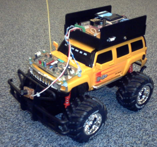
Packaged prototype mounted on remote-control car.
The roof of the R/C vehicle was drilled to mount the box with four long screws. The battery pack was fastened to the back of the vehicle using strong adhesive tape. The sensor modules were protected inside plastic bags, with the a small opening to expose the sensing element, and fixed to the in the front of the vehicle using reusable adhesive material.
Software Setup
This chapter describes the software environment used to support the feral robot prototype, both in terms of the underlying operating system (GNU/Linux for the gumstix platform) and the actual client application implementing the feral robot behaviour (sensing, reading GPS, sending data to server).
The first part deals with cross-compiling the software and setting up the operating system for the gumstix computers. The second part looks at the implementation of the feral robot client software.
Gumstix Linux
The gumstix hardware platform is supported by customized GNU/Linux distribution based on the Buildroot system -- "a set of Makefiles and patches that makes it easy generate a cross-compilation toolchain and root filesystem for [a] target Linux system using the uClibc C library" -- and the U-Boot boot-loader. The evolution of the gumstix distribution (or buildroot) is maintained under version control with Subversion, and the repository is hosted at http://svn.gumstix.com.
To develop applications for gumstix platforms it is recommended to use a Linux-based host system with a fully-featured GNU software development environment properly set up (autoconf, make, gcc, etc), including the Subversion tools (svn, etc). Alternatively, Microsoft Windows with COLINUX can be used as host system for gumstix development. The host must be connected to the Internet in order to interact with the Subversion repository and download software packages during the build process.
There are several ways to gain command-line access the GNU/Linux system on a gumstix, but the most powerful (as it also allows access to the boot-loader) and failsafe is usually via the serial console. For this, the host computer must be connected to the gumstix's serial console port with a null-modem cable. The default parameters for the serial terminal emulator on the host should be the following: 115200 bps, no parity, 8 data bits and without flow-control.
More details about programming and building gumstix systems is available at the community website and technical support can be obtained through the user community mailing list.
Main Buildroot Trunk
The main development trunk in the gumstix Subversion repository contains the latest version of the generic default buildroot to generate a GNU/Linux operating system image suitable for installation on gumstix devices. The following command would to check out the latest gumstix buildroot into the gumstix-buildroot/ sub-directory:
svn co http://svn.gumstix.com/gumstix-buildroot/trunk gumstix-buildroot
The next sequence of commands would build the cross-compilation toolchain (basically gcc for the ARM processor architecture), compile the GNU/Linux operating system and applications and, finally, package it into a root filesystem ready to install on the gumstix hardware:
cd gumstix-buildroot
make
If all goes well, gumstix-buildroot/ will contain the following items [2]:
- Builbroot source from the gumstix repository:
- Makefile: main configuration file for the buildroot system, that defines the procedure to build a suitable cross-compiler toolchain (for ARM) on the host computer, as well as which software packages to compile into the root filesystem for installation on a target gumstix device.
- make/: contains a sub-makefile (with .mk suffix) for each individual software packages (or projects) available for inclusion in a gumstix root filesystem -- such as the Linux kernel, libraries and other operating system components, utility programs and applications. These sub-makefile define instructions on how to download, configure, compile (usually by invoking the package's own build scripts with the environment correctly set up for cross-compilation) and install these software projects in the root filesystem structure.
- sources/: contains the skeleton of the directory tree produced by the buildroot (target_skeleton/) with template files for inclusion on the root filesystem (e.g. /etc/ configuration files and scripts), as well as patches for the Linux kernel (in kernel-patches/) and other patch files necessary to make the source code of certain software packages suitable for cross-compilation to the target CPU architecture (ARM in this case).
- Generated by the build process (make command):
- sources/dl/: source code for individual software packages downloaded from the Internet during the build process (make/*.mk), usually compressed tarball format.
- toolchain_build_arm_nofpu/: working directory for the build process of the cross-compiler and C library.
- build_arm_nofpu/: contains the output of the build process of individual software packages, with a working directory for each project being built (other than cross-compiler and C library), as well as two special sub-directories, described below:
- build_arm_nofpu/root/: contains the directory tree and files (initially seeded from sources/target_skeleton/) used to generate, in the very final step of the build process, the root filesystem image which will eventually be installed on a target gumstix computer. The sub-makefiles of most software projects will install binaries, dynamic libraries, runtime data and configuration files, etc in this directory tree, under pathnames as they will appear on the gumstix (for example, build_arm_nofpu/root/bin/busybox will become /bin/busybox in the gumstix filesystem).
- build_arm_nofpu/staging_dir/: central repository for build output which is further needed as part of the build process, such as the cross-compiler, binutils, libraries, include files. If a software package generates static or dynamic libraries, they should be placed in this sub-directory along with their relevant headers files; dynamic libraries should obviously also be installed in the build_arm_nofpu/root/ directory as well.
- root_fs_arm_nofpu: binary image of the target root filesystem, containing the GNU/Linux operating system and applications built during the cross-compilation process. Basically this should contain a copy of everything that the gumstix needs at runtime, but nothing that is only required only at compile-time. The filesystem-building tool (mkfs.jffs2) operates on the build_arm_nofpu/root/ directory tree and picks up everything in it, then applies the details from sources/device_table.txt. This file can be loaded to the gumstix through the U-Boot boot-loader and then written to its flash memory to install the new root filesystem (this process is described in Flashing a New Software Image).
- u-boot.bin: target binary for the gumstix U-Boot boot-loader.
| [2] | Based on information from http://www.gumstix.org/tikiwiki/tiki-index.php?page=buildroot |
Feral Robot Buildroot Branch
Besides the main gumstix buildroot development trunk, a structure is defined in the Subversion repository for branching different buildroot configurations to meet or implement a specific project's requirements. Several branches can coexist in the repository and be developed independently in parallel, while changes can be merged back and forth between branches or the main trunk.
For this prototype such a branch was created on the gumstix hosted Subversion, not only to track modifications to the custom buildroot's configuration, but mainly to ease the process importing bug-fixes or new features developed in the main trunk (after the has branching occurred). So to download [3] and build a working copy of this customized "Feral Robot" buildroot branch, including extra software for the robostix board (further described in Robostix ADC), the following sequence of commands must be issued:
mkdir feral-robot
cd feral-robot
svn co http://svn.gumstix.com/gumstix-buildroot/branches/users/ddiall/robostix robostix
svn co http://svn.gumstix.com/gumstix-buildroot/branches/users/ddiall/feral-robot \
        gumstix-buildroot
cd gumstix-buildroot
make
| [3] | To work around any potential problem with gumstix's Subversion repository, a snapshot of the feral robot branch is available at http://socialtapestries.net/feralrobots/software/gumstix (revision 853, at the time of this writing). |
The structure of the buildroot system was described in greater detail in the previous section. The full range of changes to the standard gumstix buildroot can be scrutinized using svn log, but below are summarized the main additions or modifications to produce a root filesystem image tailored for this feral robot prototype:
- Created make/utrobot.mk to download, compile and install the actual feral robot client software (described in Client Application).
- Created make/robostix.mk to download, compile and install software to enable communication between the gumstix and the robostix boards, via their interconnected serial ports.
- Created make/orinoco.mk to download, compile and install Linux ORiNOCO driver on the gumstix to provide support for the Symbol Spectrum24 wi-fi card. The attempt was unsuccessful in the amount of time available [4].
- Tweaked make/gpsd.mk to update the GPS daemon (gpsd) and access library (libgps) to the latest version (2.30) and configure support for NMEA-compliant receivers.
- Defined additional TARGETS in the main Makefile to include programs and libraries required for the feral robot client system (utrobot, robostix, uisp, gpsd and libgps), as well as some extra troubleshooting tools (e.g. tcpdump, etc).
- Changed the default configuration to enable the CompactFlash slot (PCMCIA) at boot time, as well as start the wi-fi interface (wlan0 in /etc/network/interfaces) assuming it is a model supported out-of-the-box.
- Created scripts, to be installed in /etc/init.d/, to run programs required by the feral robot client:
- s99local: designed to start the GPS daemon (gpsd) and the feral robot client (utrobot) at gumstix boot time.
- gps: establishes a bluetooth serial connection with specified GPS receiver and launches gpsd.
- utrobot: sets up the environment to run the feral robot client application with the correct parameters (UT server, MAC address for robot id, robostix ADC serial port, status and data log file locations).
- ntp: updates the system time from an NTP server. This script is actually triggered when a network interface is brought up (defined in /etc/network/interfaces) to ensure that it is possible to contact the remote NTP server.
- Replaced the Unix "message of the day" (in``/etc/motd``) to display instructions on how to further customize/configure the feral robot gumstix system:
Welcome to Gumstix, implementing the Urban Tapestries FERAL ROBOT!
==========================================================================

Do not forget to change the root password with the 'passwd' command.

Change the hostname in /etc/hostname and update /etc/hosts accordingly.

Set up the ESSID in /etc/pcmcia/wireless.opts to match the wifi network.
If there is no DHCP server, set IP for 'wlan0' in /etc/network/interfaces.

Update NTPSERVER in /etc/init.d/ntp to address of the local time server.

Adjust the /etc/init.d/gps script to set-up the connection to the GPS
receiver (set receiver's bluetooth MAC address in the variable GPS_BTADDR).

In /etc/init.d/utrobot, set UT_SERVER to the Feral Robot server address
and NET_IF to the interface name to be used as the robot id (MAC address).
Rename the file s99local in /etc/init.d/ to S99local (notice capital 'S').

[This information is stored in /etc/motd, which can be deleted afterwards.]
The current feral robot buildroot configuration produces a root filesystem image of roughly 5MB. Non-mandatory items in the main Makefile are marked with the comment "OPTIONAL", therefore it should be safe to exclude from the root filesystem to conserve space in the gumstix flash memory.
| [4] | It is probably worth trying to compile the ORiNOCO driver with the latest Linux kernel version (2.6.14) now included in the mainstream gumstix buildroot. |
Flashing a New Software Image
A new software image (root filesystem) can be loaded onto a gumstix computer by accessing its boot-loader via the serial console and using the Kermit file transfer protocol.
The sequence below illustrates the commands necessary to transfer a root filesystem image to U-Boot and then commit it to the gumstix flash memory [5]. It is assumed that the host is connected to the console via port /dev/ttyUSB0 and a terminal emulator is used, such as kermit, with the correct parameters (115200,n,8). The symbol $ represents the host's shell prompt, and > the kermit prompt:
$ kermit -l /dev/ttyUSB0
> set carrier-watch off
> set speed 115200
> set reliable
> connect
The above commands should connect to the gumstix console with the right setup. Once connected to the console, the user can interrupt U-Boot by pressing a key during a (default) 2-second delay, before the Linux boot process is started (reset power to gumstix if necessary). The U-Boot prompt, GUM>, should appear:
GUM> loadb a2000000
After entering the above command, U-Boot is waiting from the transfer to begin. Type the sequence "CTRL-\ c" to return to to kermit and then the following (replacing /path/to/ with the correct location of root_fs_arm_nofpu):
> robust
> send /path/to/root_fs_arm_nofpu
This will start the transfer; after it is completed with success, reconnect to U-Boot and enter the commands below to erase everything except U-Boot itself (protected), copy the transferred software image to flash and boot the with the new root filesystem:
> connect
GUM> protect on 1:0-1
GUM> jerase all
GUM> cp.b a2000000 40000 ${filesize}
GUM> boot
| [5] | Based on information from http://www.gumstix.org/tikiwiki/tiki-index.php?page=tutorial |
Robostix ADC
There is no analog to digital conversion (ADC) capability directly available on the main gumstix processor board. Thus, the robostix add-on board was used in this prototype, due to the ADC functionality present in its AVR ATmega128 microcontroller.
As described earlier, the gumstix and robostix boards are interconnected via their serial ports -- STUART (/dev/ttyS2) and UART0, respectively -- making data exchange between software running on both processors possible. This feature is exploited to give the feral robot client application (running on gumstix) access to sensors attached to any ADC channels of the robostix.
Compiling ADC Protocol
Basically, the communication protocol on the robostix side consists of waiting for incoming ASCII characters on UART0, that represent ADC channel numbers (from '0' to '7'), and responding with the current voltage value on that ADC channel, in hexadecimal format encoded as an ASCII string (e.g. "0x03f9"). On the robostix's ATmega128 this function is implemented with an endless loop in a C program, named Read-ADC.
This program and other software for robostix can be downloaded from the gumstix repository [6] as was shown in Feral Robot Buildroot Branch (robostix/ sub-directory of feral-robot/ in the example procedure). To compile Read-ADC for the robostix an appropriate cross-compiler, such as avr-gcc, must be installed on the host computer:
cd feral-robot/robostix/Read-ADC
make
Programming Robostix
After compilation, the resulting Read-ADC.hex file must be programmed (i.e. flashed) to robostix's ATmega128. Several possible methods to program microcontrollers of the AVR family do exist, and the ones applicable to robostix, are described at http://gumstix.org/tikiwiki...
However, in this case the most straightforward way of doing this is to take advantage of the gumstix/robostix serial interconnection setup to perform in-system programming (ISP) of the software image, directly from the GNU/Linux system running on the gumstix. First, the .hex image file must be transferred from the host computer to the gumstix by console (Kermit) or network (SSH), and then (on the gumstix) use the uisp command-line tool:
uisp --wr_fuse_l=0xbf --wr_fuse_h=0xc9 --wr_fuse_e=0xff
uisp --erase --upload if=Read-ADC.hex
| [6] | The branch http://svn.gumstix.com/gumstix-buildroot/branches/users/ddiall/robostix was copied from http://svn.gumstix.com/gumstix-buildroot/branches/projects/robostix. The Read-ADC/ sub-directory was added and gumstix/ (which contains scripts and drivers) was tweaked to be compiled from within the buildroot. |
Client Application
The utrobot application forms the core of the current feral robot behaviour -- sampling its attached environmental sensors, reading the GPS position and sending data to the UT server.
Integration with Gumstix
The package, hosted at http://socialtapestries.net/feralrobots/software/utrobot-1.0.tar.gz, is automatically downloaded and cross-compiled as part of the feral robot buildroot (by the make/utrobot.mk sub-makefile, see Feral Robot Buildroot Branch).
This application requires TCP/IP access to an active GPS daemon (gpsd), either running locally (default) or over a network connection. Also the serial port of the robostix may have to be specified to access the sensors. Finally, the robot id (MAC address) and remote UT server address must be specified on the command-line -- on the gumstix this is done by a wrapper script.
For reference, below is presented the application's embedded usage instructions:
Usage: utrobot -i hwaddr -u addr[:port] [-g addr[:port]] [-a serial_port] [-ldvh]

  -i hwaddr        Robot id as MAC address (6 bytes in hex)
  -u addr[:port]   UT server (default port: 1979)
  -g addr[:port]   GPSD server (default: 127.0.0.1:2947)
  -a serial_port   Serial port for ADC access (default: /dev/ttyS2)
  -l               Log sensor data to standard output (stdout)
  -v               Print extra information (on stderr)
  -d               Print debugging information (on stderr)
  -V               Show version, then exit
  -h               Show this help message, then exit

More information on Feral Robots at http://socialtapestries.net/feralrobots/
Source Code
The source code for utrobot relies on GNU's autotools for its build system to enhance portability across platforms. The compilation of this package is similar to that of other common open source projects and, besides a standard Unix environment, only requires the gpsd access libraries and header files:
gunzip -C utrobot-1.0.tar.gz | tar xvf -
cd utrobot-1.0
./configure
make
The main modules of C code in the utrobot application are briefly described below (refer to source code for further information):
- adchw.*: implements the communication protocol with the robostix ADC device (explained in Robostix ADC). If testing on a system (e.g. host computer) that does not have a robostix hooked on a serial port, the make step can be changed to "make CFLAGS=-DDUMMY_ADC", which disables interaction with the ADC component and returns a constant (dummy) value instead.
- sensordef.*: defines a data structure that has the following essential function:
- specify what type of sensors are connected to which ADC channels, whether they are active or not, and whether their data should be sent to the UT server or not;
- provide pointers to convenient handler functions, one to convert the digitized voltage value returned by the ADC (integer) to an actual physical unit reported by that sensor (float), and another to process the converted value (triggering possible further actions if necessary, e.g. shutdown if battery voltage is below a certain threshold).
- utrobot.*: application entry point that performs command-line parsing, initializes subsystems (open robostix serial port, establish TCP connection with gpsd, open UDP socket for UT server, etc) and then enters the main control loop. The loop is driven by the sensor_defs structure to sample sensors, acquire GPS position, assemble and timestamp packet to send to server.
- logger.*: implements a lightweight data logging infrastructure that allows filtering the granularity of detail of information printed during program execution (error, warning, info, debug, etc).
Appendix
Packet Format
The client/server communication protocol uses the UDP transport over IP, and the Urban Tapestries server listens on port 1979 by default. The following fields are specified in packet format (version 1):
| Field | Size | Notes |
|---|---|---|
| Version | 4 bits | Protocol version, must be 1 |
| GPS fix | 1 bit | Whether GPS has a fix (i.e. positioning data is valid) |
| [Reserved] | 11 bits | Reserved for use in future versions |
| Robot id | 6 bytes | Standard network interface MAC address |
| Latitude | 4 bytes | Network byte-ordered IEEE-754 float |
| Longitude | 4 bytes | Network byte-ordered IEEE-754 float |
| Timestamp | 4 bytes | Network byte-ordered long, with Unix timestamp (seconds) |
| Sensor type | 4 bytes | Type defined in UT database (ASCII string) |
| Sensor value | 4 bytes | Network byte-ordered IEEE-754 float |
Circuit Details
A set of Gerber files [7] suitable for producing printed circuit boards (PCB) are available for download from http://socialtapestries.net/feralrobots/docs/. Below is presented a snapshot of the circuit's layout:
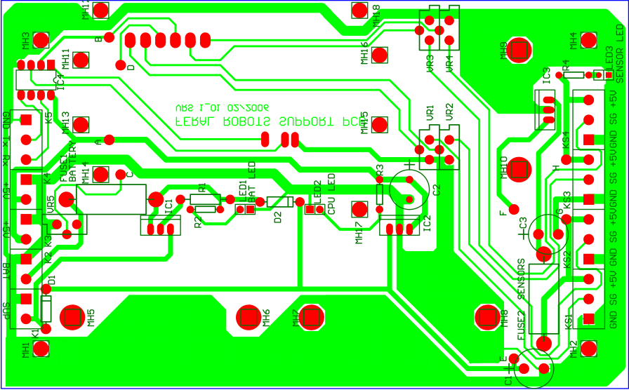
Layout of the support PCB.
During the prototyping phase, it was deemed to be more flexible to experiment with the various possibilities of the circuit on a general purpose strip board. The design options were as follows:
1. Provide power to the gusmtix stack assembly
The processor board and its peripherals required a clean 5V supply in order to feed their internal 3.3V regulators. It was not clear how much current would be required though. Experimentation with the prototype showed that a current of 800mA would be required. This meant that the use of a switch mode power supply circuit would not be necessary as its linear alternative was much simpler and lower cost to implement. In practice the line regulation provided was satisfactory, but the solution lead to two problems: the regulator generated a lot of heat, and the internal Hirose connector provided a rather high impedance path to the supply current.
The large amount of heat generated was dealt with the choice of a bigger heatsink. A heatsink with a thermal resistance of 3.7 degrees per dissipated watt was finally chosen, thus ensuring the reliable operation of the circuit beyond the winter months.
The relatively high impedance of the Hirose connector manifested itself through unexpected resets occuring during the power-up sequence of the wi-fi card. A sudden drop to the overall supply voltage activated the reset circuit of the processor. The solution to the problem was to distribute the current to the power hungry parts of the assembly via an external wire. In this way, the supply by-passed the Hirose connector and the voltage drop was minimised.
2. Provide power to the sensors
Power to the sensors was provided by a second linear regulator. Because the overall power consumption was within the limits of the regulator (less than 1A), the same heat dissipation solution was applied as in the case a, above. A fuse was provided towards the sensor boards in order to avoid any problems that might have been caused by a short circuit occuring on the external load.
3. Charge and maintain the battery cells
The choice of batteries was rather limited to NiMH cells due to their good performance/price ratio. Their weight was not an issue so Li-based options were ruled out. A constant current source providing charging current to 1/10 of the capacity was formed. Their capacity (2000mAh) would provide enough charge for a significant number of readings to be sent to the server, but would not provide the necessary power for the sensor warm-up period. The circuit would have to be powered by the external wall transformer during that period. A fuse was included towards the battery connection so as to protect both the battery and the PCB from any potential short circuits.
4. Provide serial console access to the gumstix system
The robostix brings out the gumstix console port on a 4-pin header. This port is a TTL level signal, so a standard TTL to RS232 level signal translator was used. No special protection was built into the circuit as the console port was expected to be connected directly to the PC within a rather well protected environment.
5. Form the mechanical host of the gumstix stack
The overall mechanical assembly of the heatsinks, the terminal block connectors and the processor boards was quite heavy. A final choice of epoxy glass pcb was made in order to cope with the weight.
Although, simple tie-wraps were used to secure the gumstix stack, a better alternative would be to make proper spacers, such as the design described at:
http://www.davehylands.com/Machinist/Projects/Gumstix-Spacer
| [7] | Various Gerber viewers are available for download on the Internet free of charge. |